Pwm converter schematic voltage Pwm voltage analog converter arduino converting konsep stackexchange Dc to dc boost converter circuit diagram using mc34063
Voltage to PWM module 0 10V/0 5V voltage to 0% 100% 1 1KHz PWM module
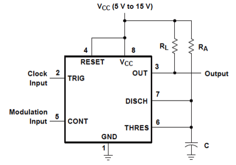
Ka7500b circuit diagram Voltage-controlled pulse width modulator (pwm) Circuit schematic diagram of the pwm dc–dc boost converter controlled
Voltage controlled pwm circuit
Voltage to pwm circuit, need to understand frequencyVoltage to pwm module 0 10v/0 5v voltage to 0% 100% 1 1khz pwm module 555 pwm circuit diagramVoltage controlled pwm circuit.
Pwm module voltage 5v 10v 1khzPwm lm358 arduino inverting circuitos electronoobs Pwm to voltage module (v1)Voltage controlled pwm circuit.

Pwm circuit analog 10vdc simple parallax forums discussion
Pwm dac output wong kerry writesPwm to voltage module (v1) Analysis of 555-based pwm circuitCircuit pwm voltage schematic frequency understand need circuitlab created using electrical.
Voltage controlled pwm circuitPwm voltage generator controlled circuit schematic full circuits 2011 drawing details following january Pwm to voltage module (v1)Pwm voltage dc converter arduino amp output circuit signal op convert slowly steadily rising but generated range.

Pwm voltage circuit frequency understand need
Pwm-to-analog signal converterA simple 555 pwm circuit with motor example Pwm voltage module circuit diagram v1 codrey circuitsDigital-to-analog converter (dac).
Module pwm voltage v1 codreyPwm converter signal circuit diagram analogue analog electronics fig block Voltage to pwm circuit, need to understand frequencyPwm 10v converter analog schematic understand works help thanks.

555 pwm dc motor controller circuit
Fan pwm to dc voltage converterPwm lm358 arduino adc opamp dimming flicker electrical circuitos electronoobs 555 pwm ltspice mathscinotes implementationSignal analog digital conversion pwm voltage dc dac output duty between modulation integrator worksheet ripple mosfet circuits determine cycle relationship.
Pwm codreyPwm circuit uses one op amp Pwm to analog 1-10v converter: help to understand how it worksArduino lm358 pwm lowpass filter voltage converter.

Konsep 34+ pwm to voltage converter
Arduino op ampPwm voltage signal modulator converter lab Pwm to voltage circuitArduino lm358 pwm lowpass filter voltage converter.
Voltage controlled pwm circuitAn isolated dac using pwm output – dangerous prototypes Voltage controlled pwm generatorSimple pwm to analog circuit (0-10vdc) — parallax forums.

Pwm motor dc controller circuit ne555 diagram transistors darlington 555 dimmer led power using transistor voltage generator switch eleccircuit battery
Digital-to-analog conversionPwm voltage controlled personified simplicity schematics Pwm fan diagram circuit converter ec voltage wiring duty open output signal connector collector controlCircuit diagram of pwm.
.


Voltage Controlled Pwm Circuit

arduino - PWM to DC converter with op amp - slowly but steadily rising
Circuit Diagram Of Pwm

Voltage Controlled Pwm Circuit

Voltage to PWM module 0 10V/0 5V voltage to 0% 100% 1 1KHz PWM module

Voltage-Controlled Pulse Width Modulator (PWM) - PWM Signal Generator